| Main | Calendar | Club Details | Repeater | Goals & History | Links | Skywarn/ARES |
| Gallery | Fox Hunt | Swap-Fest | Weather | Contacts | Other Modes | VE Testing |
| Projects | Digital Interface | Swap & Shop |
|
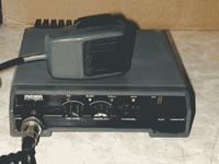
Maxon SM-3010
By Joe Loucka AG4QC
The Maxon SM-3010 is a 6 or 8 channel commercial VHF radio available on the surplus market. It's normal used in public service but easily converted to Amateur Radio service. The following is a quick introduction to it's conversion. PLEASE venture at your own risk! Things to know:
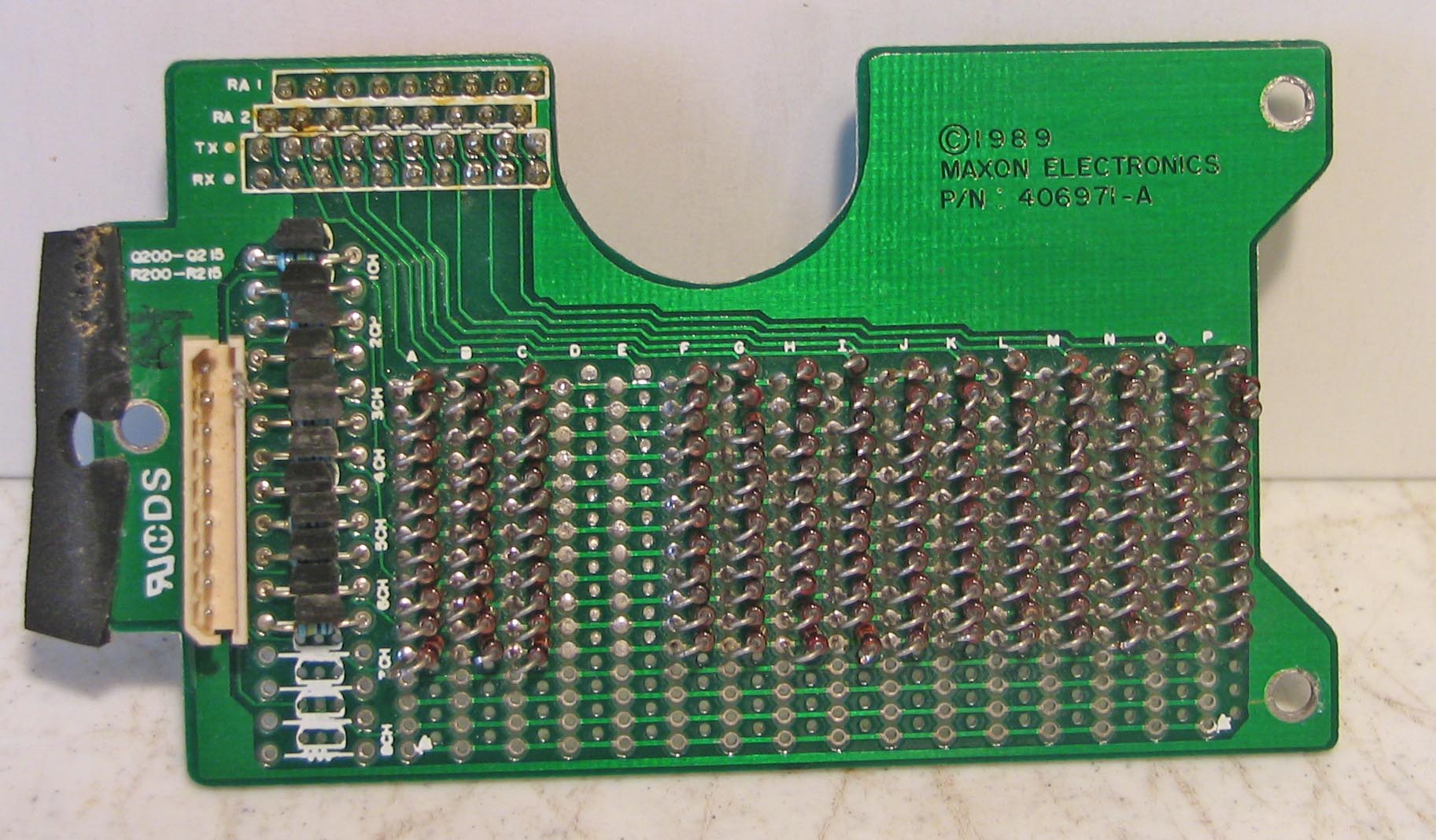
Knowing the above you can figure out the diode
combinations for any frequency. The diode board looks like this: If you cut a diode, It's as good as it not being there. If you want to change the frequency at a later date, simply solder the cut back together. The diode combinations are derived by doing the following. Take the frequency you want and divide it by the prescaler (64). Now divide that by the channel spacing (5000) This will give you a number in the 200-400 range. Take the WHOLE number and use that to fill table "N". Now take the remainder and multiply that by 64 and that will be used in table "A". Don't get too excited, we will run through a few examples in a second. Here are the two tables.
Now for example.. We want to use this radio on a repeater on 147.105 MHz This repeater has the repeater split 600 KHz up. So we transmit on 147.705 MHz Using the above we come out with:
Now we need to fill the tables.. The value 461 needs to be represented in table "N" This is a binary representation. The easiest way to do that is use the largest numbers from the table to subtract that value from the number until it's gone.
Now lets fill table "A" The value needs to be 37
This finishes our diode cut list. Your tables should look like this:
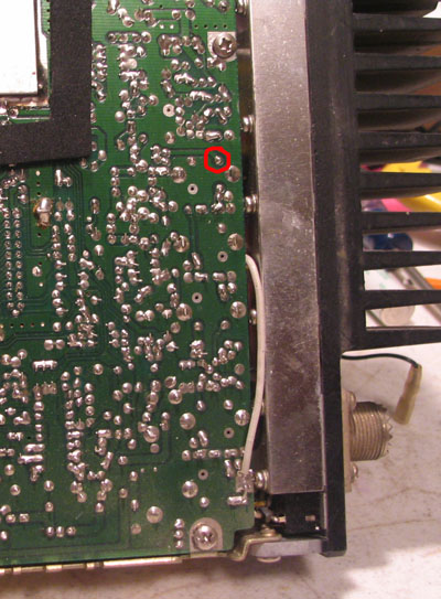
To check your work.. Add up all the values in table "N" and it should equal your original whole number.. So, 256+128+64+8+4+1=461 Do the same thing to check your work in table "A". 32+4+1=37. Now lest see if this is really the frequency we want. Take the number from table "N" (461) and multiply by 64. 461*64=29504. Take this number and ADD the value from table "A". 29504+37=29541. Now multiply the answer by 5000. This should be your frequency. 29541*5000=147705000 If all the above checks out, lets get into the radio and make it work. You will notice that the two tables have rows for Diodes. If there is a "X" in that field the diode that corresponds to that value needs to be cut. If there is nothing in that row, then that diode needs to stay. (Note: diodes in position D & E are always missing - cut.. Lets take a closer look at the diode board. Click on the
picture for a better look. In this case lets set the first channel to transmit on
147.705 as we figured out in the above tables. Because these are used
radios, some diodes are already cut. It might be a good idea to soldier
all the diode cuts back together and then just cut the ones you want.
No matter how you do it. You only want the 9 diodes cut. For
simplicity sake, lets say we have whole diodes, they were either not cut
or we soldered them back together. Connect a dummy load to the antenna. This radio is rated
at 30 watts, but most put out a bit more. Now flip the channel
selector to 1 and push the microphone PTT. If you're lucky, it will
transmit. If that's true, continue to the receiver section of this
document. This is what the adjustment portion of the radio looks
like. The top is the PLL adjust for the receiver. The one slightly and towards the middle is the transmitter. The one on the left and bottom is the common PLL. I recommend you adjust the common first. If you have a frequency counter, lay the counter probe along side the bottom of the metal can. It will probably read in the 140 MHZ range. Adjust the COM until it's in the 133 MHz or so range. If you don't have a counter, make slow adjustments and plug the diode board back in and see if you have lock. There is some interaction between the transmit PLL adjustment and the common. So they both might need to be tweaked. You can tell if you are getting close, as the further away you are, the faster the red transmit light blinks. I highly recommend you make a extender cable OR do the receiver part first as you can drill a hole in the diode board as the receiver adjustment is under a part of the board that has no diodes and so can be adjusted while in place. Once you have lock ( and it's not as bad as it sounds) it should lock on all your 2 meter frequencies. The first time I tried this it took me about 4 times to get lock. Receiver frequency.
Your table "N and "A" should look like this:
Cut the diodes in the SECOND row to correspond to your table. This should allow you to receive the repeater frequency. Crank up the radio and flip it to channel 1. Hopefully, the transmit red led will be out, meaning the PLL is locked. If it's blinking, then the receiver PLL needs to be tweaked. This is the top left adjustment below the diode board. You can either remove the board, make a small tweak and put the board back until you get lock. Or build and extender cable and do it the easy way. Or do what I first did and drill a hold in the diode board right over the adjustment location. There is plenty of room and you should be able to mark the location, remove the board and drill the hole without damaging any electronics. All the diode traces are external to that location. Anyway, with both the transmit and receive frequency in the radio, you should be good to go into the repeater. Well, unless you use CTCSS on the repeater.. But hey, this is the easy part.. Look around and find the little CTCSS board. It's on a board that shares a screw with the diode board you have just been updating.. On there is a 6 position switch. Use the following table to set your PL..
Using the above table.. Lets set the tone for 156.7.. Looking down the table we find it is 0-1-1-0-1-0 this relates to the switch on the board as:
Notice the switch is backwards.. 0 is ON and 1 is OFF. Also switch 6 corresponds to the first bit. and it works backwards from there.. Yeah, I know it's confusing, but it's easer then figuring out which diodes to cut! One thing to keep in mind is this switch sets the CTCSS for ALL channels. This could be a problem if you access multiple repeaters with different tones. You 'could' mount the switch external and make it available that way.. Or use the extra diode slots on the diode board and switch the tones around that way.. That's certainly doable and maybe some time I'll write something on that. This completes the transition of the radio. Do the same as all the above for each channel., remembering the channel diodes count from the top down, with the first row the transmit and the second the receive. That makes the bottom row of diodes on the bottom row of the board the receive for channel 6. Alignment With the signal injected, use a scope or rf probe to
measure the voltage on the trace of the 5 can's.. One trace can work for
all the alignment. See picture below. I normally just solder a short
wire to the trace so I can then flip the radio over and align the can's. With the probe on the traces, adjust the cores of the 5 can's that are across the top of the picture below. Adjust them for the highest signal level. Go back and forth, as there is a little interaction between them. Also adjust the two coils that are below the last big can. Do not try to align the smaller cans as they should be fine.
The green pot that is to the right of the last big can is the power control. Also, you can tweek the deviation by adjusting the white pot that is directly below the VCO can you adjusted a few pictures above. Well, that's about it.. Once you set a few of these up. it takes about 20 min;'s to do a complete radio. I talked about a repeater in this document. But of course it works on simplex also. If this is a PDF document, drop by our website http://chestercountyarc.com and get the latest version of this document and much more! If you have any questions, feel free to drop me a e-mail at joel@cyberbest.com Joe Loucka AG4QC Update on 4/9/2006 |