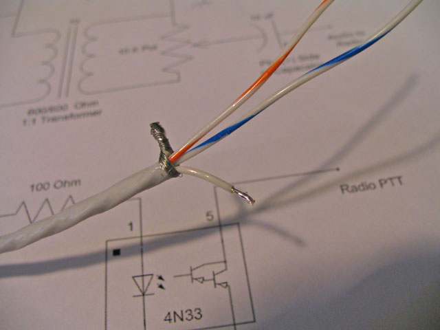
| Carefully strip back about 4 inches of the outer insulation on the white radio cable. Using a sharp ended 'device' starting at the cut end, un-weave the shield down to the insulation. Pull the wires away from the shield and twist the shield together to make one wire. Cut the shield wire to be about 1/2 inch long and completely tin the remaining shield. Also cut the solid white wire to be about 1 inch long and strip 1/4 inch and tin. |  |
The other end of this cable goes to the connectors for your radio. Because every radio has a different connector, I can't be of much help in this document. But the general instructions would be: - The white/blue wire goes to the radio audio out or speaker
- The white/orange wire goes to the radio audio in or microphone. Remember the pot should be set in the center to start and then tuned for best transmission.
- The solid white wire goes to the radio's PTT.
- Then the shield goes to the radio ground.
This completes the interface and you should be able to do some basic testing. While testing is very subjective, I suggest you do the following. - Fire up the computer and bring up Digipan -- You should have loaded the software when you built the serial cable.
- Plug the orange cable into the computer's line-in or microphone jack.
- Plug the radio cable into your radio.
- Tune the radio to 14.070 MHZ and you should see some activity on the water falls on Digipan. With no audio it will be dark blue but audio/noise will cause it to turn yellow or red. If you see red or yellow vertical lines that look like train tracks that's great, as its a PSK31 signal. Move the mouse and clicking on the train tracks should give you the text of the QSO. You might have to use your computer's control panel to adjust the soundcard volume level for the microphone or line-in for best levels,
- If you don't see any activity on the water falls, look for something wrong with the audio lines. This is the very top of the schematic and only involves the soundcard line in cable, transformer T1 and the audio in from the radio.
- Now that you have the receive working, let's test the PTT
- Plug in the serial cable at your computer. Click on the CQ button at the top and the LED should light and your radio should start transmitting. It will transmit a short while and then stop when the CQ's stop. If this works, then great. If not, we tested the serial cable and opto isolator and LED in the test of the serial port cable. So all that's left is the radio PTT. If all checks out okay but still doesn't work, check to see if you have a positive voltage on the PTT (white) wire. If you short the shield to the PTT wire it should trigger the radio to transmit. It could be the radio needs a better PTT line. I have an interface reed relay modification that might help. Contact me for more information.
- Now we need to set the transmit level. Plug in the white audio cable to the computer line-out or speaker. Make sure the interface pot is set at about the 1/2 way point.
- Click on CQ and see what happens. If you have another radio listen to see if you hear your signal. Turn the computer soundcard line-out or speaker level until the ALC just starts to move, This is about the best level. If in doubt of your level, make a contact on PSK and have them tell you what your tracks look like. If they're wide, then you would need to turn down your level. It's best to error on the low side.
A great place to find the pins of your radio is http://usinterface.com/naviusa_007.htm
Known radio connectors ( Please check your manual to make sure these are correct ) | Radio | Audio Out W/BL | Ground | Audio In W/OR | PTT White | | Kenwood TS-140S, 450, 570D ,690 use 13-pin DIN male | 3 | 8 | 11 | 9 | | Icom FT-718 13-pin DIN male | 12 | 2 | 11 | 3 | | Yaesu FT-817 6-pin mini-DIN male | 5 | 2 | 1 | 3 | | Icom FT-756, use 8-pin DIN male | 5 | 2 | 4 | 3 | If all the above works, then happy Digital Mode. Once you are comfortable let'st put this baby in a box .. The Club Website will have the latest version of these directions.
Take a look at http://chestercountyarc.com/digital or contact me at joel@cyberbest.com |