 | |||||||||||||||
|
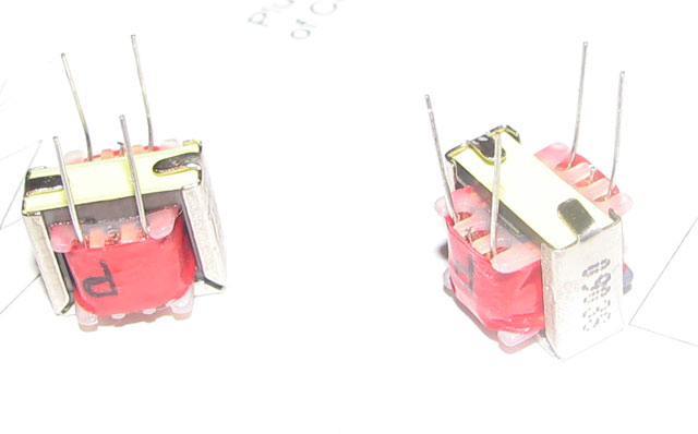
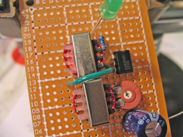
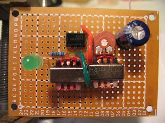
Building the Digital interface Notice the perfboard is a little sticky. That’s a coating of soldering rosin to allow easer soldering and also keeps the copper from corroding. There is no need to clean the board. As a matter of fact its better if you leave the ‘stickiness’ alone. Notice the board has both row numbers and column designations. This can help in using the pictures to figuring where to insert components. So lets get started:From your basic kit of parts, pull out both transformers. You will notice they have 6 wires. The middle wire is a center tap of the two transformer windings and not used or needed. To make life less confusing, carefully clip off the two center wires as seen in the photo. Also bend over the metal tabs so the transformer will rest flat on board. Both transformers are the same. Notice there is a "P" on one side of the transformer. Make sure the "P" is towards the left when the transformers are mounted. Straighten the 4 wires and make sure they are pointed straight down. Now insert one of the transformers so the wires on the "P" side go through the holes at F-8 and F-10 and the other side goes through at J-8 and J-10. Now mount the other one at F-14 and F-16. Use holes J-16 and J-14 for the other side. Then bend over the wires to hold it in place as in the picture. Notice the wires in the middle are bent towards each other as they get soldered together to form both the radio and computer common ground.
Now mount the Pot and the Capacitor. The pot should be centered next to the transformer. The leads of the pot are a tight fit into the board but they will snap in place when pushed with some pressure. Notice the pots placement. The holes should line up with O-9 and K-8 and K-10. This should make the mounting look like the picture below and two pins on the pot would be right next to the leads of the transformer. Now mount the capacitor as indicated in the picture. The leads should go through holes N-4 and N-6. Notice the Minus side of the capacitor is positioned towards the pot. N-6
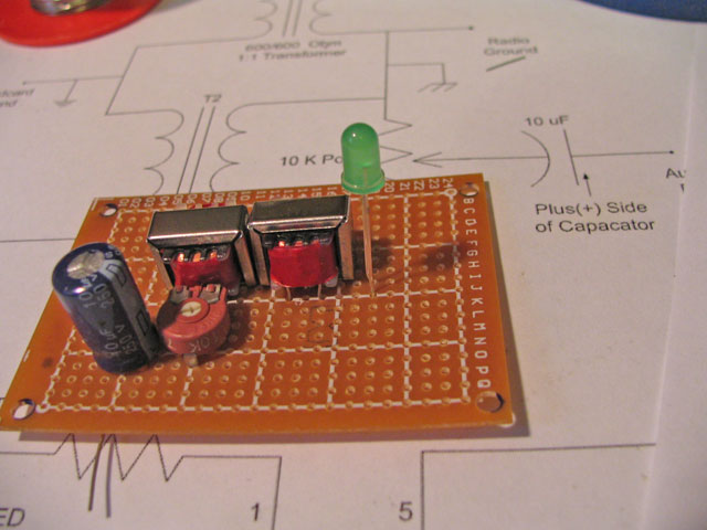
Next we mount the green LED. This would go through holes J-19 and I-19. Make sure that the shorter LED wire is the one in hole J-19 The LED has to go through the top of the box, so make sure it's mounted so the bottom of the LED is about at the level of the top of the capacitor. It's not critical, but error on the 'leave it higher' side if needed. When you mount the board in the box, you can always bend the wires to make it shorter if too high. But if it's too short.. Well.... I have extra's.. Solder both LED wires but don't cut then off yet. Next we mount the Opto-Isolator Socket. (Notice the picture shows the actual chip. I didn't have sockets at the time I built the proto-type). Position the 6 pin socket so that the pins go through L-13,14,and 15 and also O-13,14 and 15 Solder all 6 leads. Notice the notch of the chip is up. If you are using a socket, solder it in place and then insert the chip in the socket, paying attention to chip orientation.
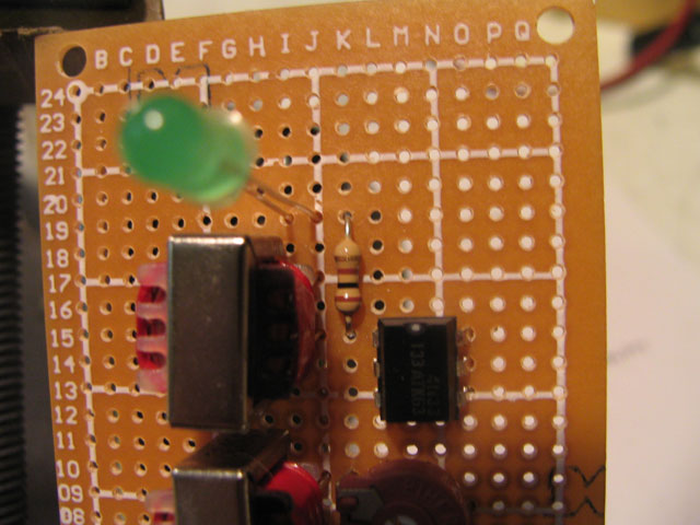
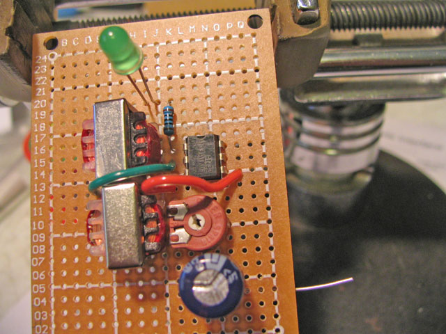
Now lets add the resistor. This is 100 Ohms. Yours might look a bit different but it's the only resistor in the kit. Insert it in the holes K -19 & K-15 The direction don't matter. One end of the resistor will be right next to the one LED wire. Allow the two to overlap and then solder them together and cut off the extra wire. The other end of the resistor will come out next to pin one of the chip. Bend it over the top of the pin and solder the two together. Trim this also.
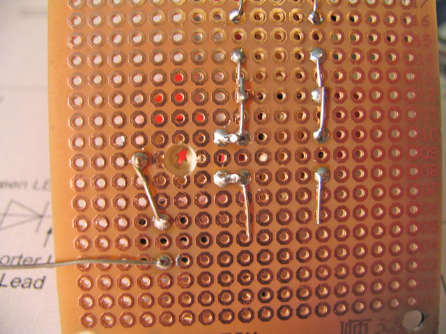
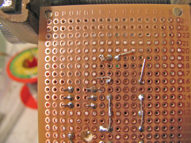
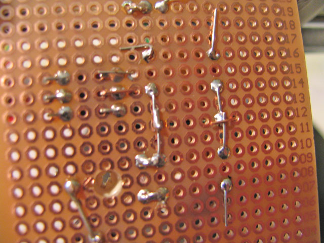
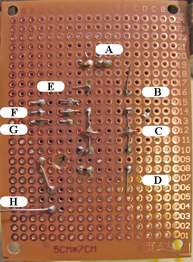
We need to get the Computer ground over to pin 2 of the chip. The easiest way is to use a jumper wire. Strip off 1/4 inch off each end of the green wire. Insert one end in hole E-12 and the other in hole K-14 One end of the wire should be next to pin 2 of the chip. Lay it over the top of pin 2 and solder the two together. The other end should be next to the long ground wires. Bend the wire over the other soldered connections and solder this also. Check to make sure pin 1 and pin 2 of the chip are not bridged with solder.
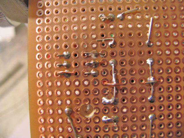
Just as above, we need to get the radio ground to pin 4 of the chip. So we will use a red wire. Strip 1/4 inch from each end of the wire. Insert one end into K-12 and the other in to P-13. One end of the red wire should be right next to the long radio ground. Bend the wire over that ground and solder. The other end should be next to pin 4 of the chip. Bend it over to be on top of pin 4 and solder. Looking at the chip from the solder side of the board, pin 1 is the upper right most pin and the bottom left most pin is 4. So the pins count clockwise. That makes the unused pin 6 at the top left.
This completes the basic Interface. It should look a lot like the pictures below.
The above tests are a basic health check. If the measurements are way off, check and correct the wiring before you continue.
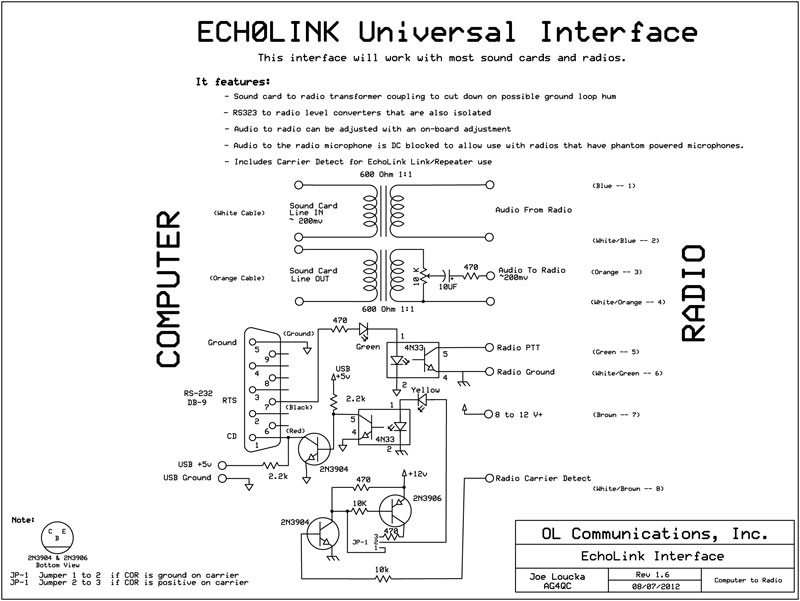
Now all you need to do is add the connecting cables. The cables attach as:
The Club Website will have the latest version of these directions. |